End of Call
End of Call
Step 1
Replace all brackets and ensure that all screws are tightened.
Step 2
Replace the top cover of the library, if it was removed.
Step 3
Slide or place the library back in its home location.
In a rack-mounted unit, ensure that the library front eyelet bracket is fastened to the rack vertical rail.
For more details, see Chapter 5, 'Installing the Rack-Mounted Tape Library'.
Step 4
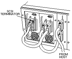
Ensure that all SCSI cables and the SCSI terminator are connected.
Make the widest possible loops in the short drive-to-drive and drive-to-controller cables (see below Figure 13).
Each device in the tape library (the tape drives and the tape library controller) has two SCSI connectors.
Each connector can be used as an in or out connector.
This lets you connect the cables so that you can make wide loops between devices, thus reducing cable stress.
 -Attention- When you attach SCSI cables, make sure that the power is turned off.
Step 5
If they were changed for any reason, make sure that the SCSI IDs for the tape drives are returned to their original values.

Figure 13. SCSI Cable Attachment on the Tape Library
Step 6
Remove the CE cartridge or any scratch cartridges from the library.
Step 7
If you removed customer cartndges, place them back in the cells from which they were removed.
Otherwise, place them randomly in any magazine cell or fixed cell (because the library front door was opened and the power was turned off, the
application software must perform a reinventory).
Step 8
Turn on the power to the tape library (if it is not already on), and ensure that initialization successfully finishes.
Step 9
Inform the customer that tape library and DLT7000 tape drives are ready for on-line operation.
Back to 
Please see the LEGAL - Trademark notice.
Feel free - send a  for any BUG on this page found - Thank you.
 -Attention- When you attach SCSI cables, make sure that the power is turned off.

