Installing Memory-module Kits - Netfinity 5600 - Type 8664
Installing Memory-module Kits
Note: To remove a memory-module kit, reverse this procedure.
Adding memory to the server is an easy way to make programs run faster.
You can increase the amount of memory in the server by installing options called
memory-module kits .
Each kit contains one industry-standard, dual-inline memory module (DIMM).
The server uses a noninterleaved memory configuration.
The server comes with a DIMM installed on the processor board in connector J1.
Notes:
- Install additional DIMMs in connectors J2, J3, and J4, in that order.
(See the following illustration for memory connector locations.)
If you mix DIMM sizes, install the largest sized DIMM in connector J1, the next largest sized
DIMM in connector J2, and so forth.
- The Netfinity 5600 server supports 128MB, 256MB, 512MB, and 1GB DIMMs.
The server supports a minimum of 128MB and a maximum of 4GB of system memory.
Only 133MHz, 3.3 V, 168-pin, 8-byte, 72-bit registered, synchronous-dynamic-random-access memory (SDRAM),
error correcting code (ECC) with x4 configuration DIMM memory complying with PC 133 Registered DIMM Specification,
Revision 1.0 or later is supported.
When installed in systems using 100MHz front-side bus processors, the memory operates at 100MHz.
- Installing or removing DIMMs changes the configuration information in the server.
Therefore, after installing or removing a DIMM, you must save the new configuration information
in the Configuration/Setup Utility program.
When you restart the server, the system displays a message indicating that the memory configuration
has changed.
Start the Configuration/Setup Utility program and select Save Settings.
See 'Using the System Configuration Utility main menu' for more information.
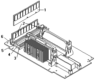
1 DIMM
2 Retaining clips
3 DIMM connector 1 (J4)
4 DIMM connector 2 (J3)
5 DIMM connector 3 (J2)
6 DIMM connector 4 (J1)
Before you begin:
To install a DIMM:
- Turn off the server and peripheral devices and disconnect all external cables and power cords
(see 'Preparing to install options'); then remove the cover.
See 'Removing the left-side cover (tower model)'
or 'Removing the cover (rack model)'.
- Locate the DIMM connectors on the processor board.
Determine the DIMM connector into which you will install the DIMM.
(See the notes at the beginning of this procedure.)
- Touch the static-protective package containing the DIMM to any unpainted metal surface on the server.
Then, remove the DIMM from the package.
Note: To avoid breaking the retaining clips or damaging the DIMM connectors, handle the clips gently.
- Install the DIMM:
- Turn the DIMM -1- so that the pins align correctly with the connector -5-.
- Insert the DIMM into the connector by pressing on one edge of the DIMM and then on the other edge of the DIMM.
Be sure to press straight into the connector.
Be sure that the retaining clips -2- snap into the closed positions.
- Make sure the retaining clips are in the closed position.
If a gap exists between the DIMM and the retaining clips, the DIMM has not been properly installed.
In this case, open the retaining clips and remove the DIMM; then, reinsert the DIMM.
- Repeat these steps for each DIMM that you install.
- If you have other options to install or remove, do so now; otherwise, go to 'Completing the installation'.
Back to 
Please see the LEGAL - Trademark notice.
Feel free - send a  for any BUG on this page found - Thank you.