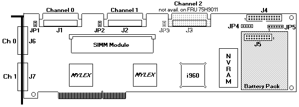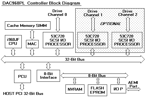

PCIRAID (DAC960PL) Connectors and Jumpers
Connector| Description
---------|---------------------------------------------------------------
J1 | Fast/Wide SCSI Connector, 68-pin, Drive Channel 0
J2 | Fast/Wide SCSI Connector, 68-pin, Drive Channel 1 (Optional)
J3 | Fast/Wide SCSI Connector, 68-pin, Drive Channel 2 (Optional)
J4 | AEMI (Array Enclosure Mgmt Interface) Port
J5 | Connector, Battery Backup Module (Optional) see NOTE-1
J6 | External Fast/wide SCSI Connector, 8mm Champ
| Drive Channel 0
J7 | External Fast/wide SCSI Connector, 8mm Champ
| Drive Channel 1 (Optional)
JP1 | SCSI Termination Jumper, Drive Channel 0
JP2 | SCSI Termination Jumper, Drive Channel 1 (Optional)
JP3 | SCSI Termination Jumper, Drive Channel 2 (Optional)
JP4 | Reserved (Factory test use only)
JP5 | Connector block, Bus/Drive Activity LEDs
-------------------------------------------------------------------------
NOTE-1 J5 is the optional cache backup module connector.
If the module is not installed in J5, a loopback plug must
be installed in it for proper operation.
External Status LED Connector (JP5)
Connector |Indicator |Meaning if ON
--------------|--------------|-------------------------------------------
JP5, Pin 1-2 |SCSI Activity |One (or more) of the SCSI channels
| |on the controller is transmitting
| |or receiving data.
--------------|--------------|-------------------------------------------
JP5 Pin 3-4 |PCI Activity |The controller is transmitting or
| |receiving data to or from the host.
--------------|--------------|-------------------------------------------
JP5 Pin 5-6 |Write Pending |The cache memory on the DAC960 holds
| |data that is more current than the
| |data on the hard drive(s).
-------------------------------------------------------------------------
External LED Connectors Jumper JP5 This six pin header provides
connection for three status LEDs, the odd-numbered pin is the +5V source (Pin 1, 3 and 5).
An external series resistor is not required for connecting LEDs.
 DATA WILL BE LOST if the system either loses power
or is reset while the Write Pending LED is ON (indicating the cache contains data
not yet written to disk). To prevent loss, install the optional cache battery backup module.
