Seagate BARRACUDA 2LP - Disk Drives


Seagate BARRACUDA 2LP - Disk Drives

Disk Types ST31250N/ND, ST31250W/WD/WC/DC, ST32550N/ND and ST32550W/WD/WC/DC 

Seagate, Seagate Technology and the Seagate logo are registered trademarks of Seagate Technologiy, Inc. 
Barracuda, SeaFAX, SeaFONE, SeaTDD and SeaBOARD are trademarks of Seagate Technology, Inc. 

The Seagate Technical Support Bulletin Board System (BBS)

Modem-Locations (8N1) 300 up to 9600 baud

  USA, Mexico, Latin America   (408) 438-8771
  England                      44-62-847-8011
  Germany                      49-89-140-9331
  Singapore                    65-292-6973
  Australia                    61-2-756-2359
  Canada                       (416) 856-5581
  France                       33-1-40-67-1034
  Korea                        82-2-556-7294


JUMPER setting for N / ND drives

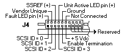
Jumper Block J4

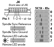
Use the J4 connector to set the SCSI ID. To change the SCSI ID, install jumpers on the appropriate pins as shown in below picture


For Synchronizing spindles, use pins 5 and 6 on the J4 connector to attach the spindle sync cable.
Use pins 3 (anode) and 4 (cathode) for a Remote LED connection.

Terminating the drive J1

ST31250N and ST32550N drives are terminated with permanently mounted IC active terminators. If you install one of these drives and it is not on the end of the SCSI bus, disable the terminators by removing the jumper from pin 5 and 6 of connector J1. If you install the drive on the end of the SCSI bus, enable termination by installing a jumper on pins 5 and 6 of connector J1.


  Use active terminators when terminating the bus.

ST31250ND and ST32550ND drives do not have internal terminators or any other way of adding internal termination to the drive. You must provide external active termination (ANSI SCSI-Alternative 2) to these drives when termination is required.

Termination Power J1

There are four possible terminator power configurations for ST31250N and ST32550N drives. You will not normally need to change this option and can leave the drive configured as it was shipped from the factory.

ST31250ND and ST32550ND drives should be configured with a jumper connecting J1 pins 1 and 3 (and no jumper on J1 pins 2 and 4).

ST31250N and ST32550N 


ST31250ND and ST32550ND 


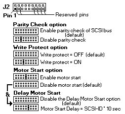
Other applicable jumper options J2


JUMPER setting for W / WD drives

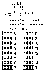
Setting the SCSI ID jumpers J5

Use the J5 connector to set the SCSI ID. To change the SCSI ID, install jumpers on the appropriate pins as shown.


Terminating the drive J1

ST31250W and ST32550W drives are terminated with permanently mounted IC active terminators. If you install one of these drives and it is not on the end of the SCSI bus, disable the terminators by removing the jumper from pin 5 and 6 of connector J1. If you install the drive on the end of the SCSI bus, enable termination by installing a jumper on pins 5 and 6 of connector J1.


  Use active terminators when terminating the bus.

ST31250WD and ST32550WD drives do not have internal terminators or any other way of adding internal termination to the drive. You must provide external active termination (ANSI SCSI-Alternative 2) to these drives when termination is required.


Termination Power J1

There are four possible terminator power configurations for ST31250W and ST32550W drives. You will not normally need to change this option and can leave the drive configured as it was shipped from the factory.

ST31250WD and ST32550WD drives should be configured with a jumper connecting J1 pins 1 and 3 (and no jumper on J1 pins 2 and 4).

ST31250N and ST32550N 


ST31250ND and ST32550ND 


For Synchronizing spindles use pins 11 and 12 on the J5 connector to attach the spindle sync cable.

Other applicable jumper options J2


JUMPER setting for WC / DC drives

Setting the SCSI ID jumpers

The SCSI ID for WC drives is normally set over the SCSI bus by the host system using connector contacts 39 (ID0), 40 (ID2), 79 (ID1) and 80 (ID3).

Terminating the drive

ST31250WC and ST32550WC drives do not have internal terminators or any other way of adding internal termination to the drive. You must provide single-ended external active termination (ANSI SCSI-2 Alternative 2).

Spindle synchronization for WC drives is normally handeled on the SCSI bus by the host system using connector contact 37 for the spindle sync reference signal. System designers may, optionally, install a spindle sync cable using pin 6 on the J4 connector to provide +SSREF.

Applicable jumper options


Barracuda 2LP Characteristics

 Characteristics          ST31250         ST32550
 -------------------------------------------------------
 Interface                Fast SCSI-2 1   Fast SCSI-2 1
 Capacity
   Unformatted            1.205.3 MB      2.541.3 MB
   Formatted 2            1.020.9 MB      2.147.4 MB
 Recording
   Cylinders (user)       3.711           3.510
   Read/write data heads  5               11
   Servo heads            1               1
   Avg bytes/track        64.160          64.160
 Seek time 3
   Average read           8.0 ms          8.0 ms
   Average write          9.0 ms          9.0 ms
 Disk rotation
   RPM                    7.200           7.200
   Average latency        4.17 ms         4.17 ms
 Internal transfer rate   47.5 to 72.0    49.4 to 72.0
   (Mbits/sec)
 Max sync. SCSI transfer rate
   N/ND                   10 Mbytes/sec   10 Mbytes/sec
   W/WD/WC/DC             20 Mbytes/sec   20 Mbytes/sec
 Multi-segmented cache    512 Kbytes      512 Kbytes
 1 Can also be operated according to SCSI-1 protocol
 2 Standard factory units are formatted as follows :
        512 data bytes per sector
          9 spare sectors per cylinder
          1 cylinder at the inner track reserved for spares
 3 Not including on-board controller overhead.
 DC power requirements  (± 5%)
 -------------------------------------------------------
                             Single-ended    Differential
                             +5V    +12V     +5V    +12V
                                         Amps

 Maximum operating current   0.93   0.6      1.17   0.6
 Max starting current
   Peak DC                   0.93   1.35     1.00   1.35
   Peak AC                   ----   1.93     ----   1.93
 Delayed motor start (max)   0.88   0.12     0.92   0.12
 Peak operating current
   Typ DC                    0.91   0.57     1.13   0.57
   Max DC                    0.93   0.60     1.17   0.60
   Max (peak)                1.00   1.56     1.95   1.56
 Track following (DC)
   at OD                     0.91   0.5      0.99   0.50
   at ID                     0.88   0.51     0.96   0.51
 Read track
   OD DC                     0.96   0.53     1.35   0.53
   AC                        1.03   0.73     1.95   0.73
 Seeking
   Typical DC                0.89   0.78     0.99   0.78
   Maximum DC                0.92   0.82     1.10   0.82
   Maximum (peak) AC         0.95   1.60     1.67   1.60


Back to  Jump to TOP-of-PAGE

Please see the LEGAL  -  Trademark notice.
Feel free - send a Email-NOTE  for any BUG on this page found - Thank you.