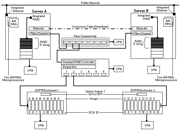
Netfinity 5500 M10 Rack Fibre Channel Cluster Example
The network-crossover cable, sometimes referred to as the cluster's heartbeat, provides the dedicated,
point-to-point communication link between the servers.
This cable connects the IBM 100/10 PCI EtherJet Adapters (one in each server) and enables the servers to continuously monitor each other's functional status.
The servers connect to the public network using the Ethernet controllers on the system boards.
Using the public-network connection and the dedicated heartbeat link together ensures that a single
network-hardware failure will not initiate a failover situation.
Notes:
Server A and Server B are configured identically.
To maintain high availability, the three hard disk drives in each server are defined as RAID level-5 logical drives using the integrated ServeRAID controller on the system board.
Other items in this example that increase the availability and reliability of the servers include the additional
memory, microprocessors, and power supplies.
Each server comes with 128 MB of memory and supports up to 2 GB of system memory.
In this example, the additional 512 MB memory kit brings the total system
memory for each server up to 640 MB, and the additional microprocessor enables symmetric
multiprocessing for each server.
Each server also comes with one, 400 Watt hot-swap power supply, but supports an additional 400 Watt hot-swap supply for power redundancy.
The maximum storage capacity 34 for each Netfinity EXP15 is 182 GB, using ten 18.2 GB hot-swap drives.
However, this example shows ten 9.1 GB hot-swap hard disk drives in each enclosure. To help maintain
high availability, the drives are grouped into four RAID level-5 logical drives (arrays A, B, C, and D).
To further increase the availability of the shared drives, each enclosure has its own hot-spare (HSP) drive.
Option Switch 1, on the rear of the EXP15 enclosures, is set to the 'Off' position. This forms one
continuous SCSI bus in each enclosure.
The Channel 1 connector on the Fibre Channel RAID Controller unit is connected to the SCSI Bus 1 IN
connector on EXP15 Enclosure 1 and the Channel 2 connector on the controller unit is connected to the
SCSI Bus 1 IN connector on EXP15 Enclosure 2.
The SCSI ID assignments for the shared hot-swap drives are controlled by the backplanes inside the
Netfinity EXP15 enclosures.
When configured as one continuous SCSI bus, the SCSI IDs alternate between low and high addresses.
These alternating IDs might cause some confusion. To avoid confusion with the SCSI IDs, consider placing a label with the SCSI IDs across the front of the drive bays.
In this example configuration, the SCSI ID assignments for each enclosure from left (bay 1) to right (bay 10) are:
0 8 1 9 2 10 3 11 4 12.
Ideally, the servers and storage enclosures are connected to different electrical circuits, however, this is rarely possible.
To help prevent the loss of data and to maintain the availability of the shared disks during
a power outage or power fluctuation, always connect the servers and expansion enclosures to uninterruptible power supplies (UPS).
The capacity of the Netfinity Rack is 42U. Each server occupies 8U, each EXP15 enclosure occupies 3U,
the Netfinity Fibre Channel Hub occupies 1U, and the Netfinity Fibre Channel RAID Controller unit occupies 4U.
You can house this 27U cluster and its support devices (such as console, keyboard, and
uninterruptible power supplies) in IBM Netfinity Racks or in industry-standard, 19-inch racks that meet
EIA-310-D standards and have minimum depths of 71.12 cm (28 inches).
(See 'Selecting the Rack Enclosures' for more information.)
Please see the LEGAL - Trademark notice.
Feel free - send a  for any BUG on this page found - Thank you.