- Select Advanced Functions from the Main Menu of the configuration program.
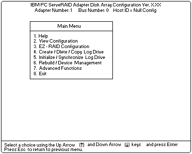
 -Important- If you already have logical drives defined that you wish to keep, go to step 2f.
The steps prior to step 2f will cause loss of data by deleting all logical drives already defined.
- Select Init/View/Synchronize Config from the Advanced Functions menu.
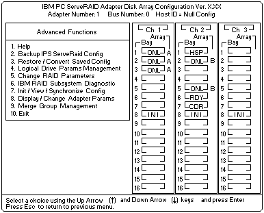
- Select Initialize Configuration to initialize the adapter configuration.
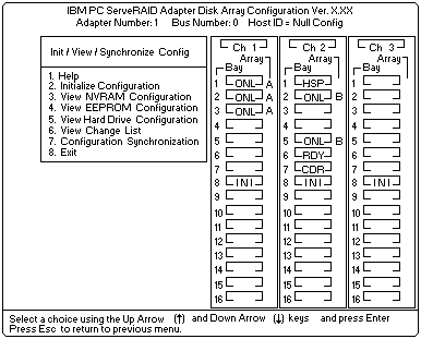
- When complete, press the Esc key to return to the Advanced Functions menu.
The Confirm pop-up window appears. - Select Yes to save the changes, or select No to return the setting to its original state; then, press Enter.
- From the Advanced Functions menu, select Change RAID Parameters and enable the unattended mode.
A screen similar to the following appears.
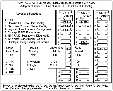
Note: For descriptions of the RAID parameters, refer to the 'IBM ServeRAID Adapter Installation and User's Guide'. - Use the Up Arrow (
 ), Down Arrow (
  ), Left Arrow (<), or Right Arrow (>) keys to highlight the
parameter you want to change; then, press Enter to change the parameter.
Note: The stripe unit size for Server B must be set to the same setting as Server A.
- When complete, press the Esc key to return to the Advanced Functions menu. The Confirm pop-up window appears.
- Select Yes to save the changes, or select No to return the setting to its original state; then, press Enter..
- From the Advanced Functions menu, select Display/Change Adapter Parameters.
A screen similar to the following appears.
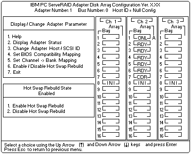
- Select Change Adapter Host/SCSI ID.
A screen similar to the following appears.
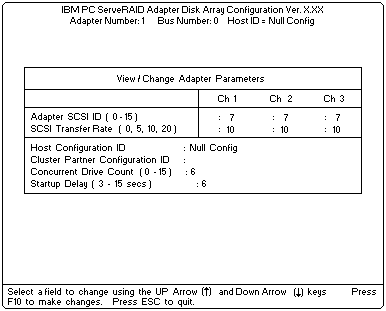
Note: Do not attempt to change the host ID on both ServeRAID II adapters in a pair at the exact same time. Doing so can cause a problem, such as a server lock-up . - To select a field on this screen, use the Up Arrow (
 ) or Down Arrow (
  ) key.
- Change the SCSI ID for the adapter on the channels that will be shared, to SCSI ID 7, the default
setting is 7.
Normally, nonshared channels are set to SCSI ID 7. -Important- If your configuration will contain multiple ServeRAID adapter pairs, each adapter Host
Configuration ID must be unique.
Do not assign a Host Configuration ID or Cluster Partner Configuration ID to adapters that do not contain any shared channels. - Enter a name for the Host Configuration ID for server B, for example, Server_B.
Note: The name of the Host Configuration ID is case-sensitive.
- Enter the name that you used for the Host Configuration ID for Server A, referred to as the Cluster
Partner Configuration ID on the screen, for example, Server_A.
You will see a screen similar to the following:Note: The name of the Cluster Partner Configuration ID is case-sensitive.
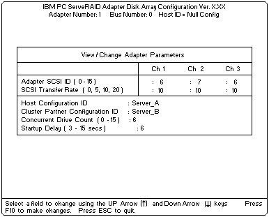
 -Important- Be sure to record the SCSI IDs, Host Configuration IDs, and Cluster Partner Configuration IDs
in a safe place for future reference.
You will need this information to recover the configuration if the ServeRAID II adapter should fail. - Record the SCSI IDs, Host Configuration IDs and the Cluster Partner Configuration IDs.
- Press F10 to exit. The Confirm pop-up window appears.
- Select Yes to save the changes, or select No to return the setting to its original state; then, press Enter.
- Continue to press Esc until you return to the Main Menu of the configuration program.
- Choose Create/Delete/Copy Log Drive from the Main Menu.
- Select Define/Undefine a Hot-Spare Drive from the Create/Delete/Copy menu.
- Select the device to be defined as a Hot-Spare Drive. Be sure that:
1) Hot spares are defined to shared channels for shared adapter pairs.
2) When selecting a hot-spare device, the device has not been defined on the partner adapter.
Record the channel and bay numbers of all arrays and HSP devices.
This information will be used during the configuration of Server B to ensure the same
devices are not defined on both systems.Notes:
a) When creating logical drives, be aware of the following way in which the information is displayed on the ServeRAID configuration program screens. You should create only one logical drive for each array when defining shared logical drives for use in a cluster.
When logical drives are created, they appear on the screen in the order they are created.
For ease of understanding, create an array and then all logical drives for that array before
you create another array.
If they are created in that order, they will appear on the screen as shown in the first figure.
(***** is other information that will appear on the screen, such as RAID level,
Write Policy, and so on, but is not needed for this explanation).
A ***** A0 ***** ***** ****** ****** *****
B ***** B0 ***** ***** ****** ****** *****
C ***** C0 ***** ***** ****** ****** *****
If logical drives are created out of order, meaning you do not follow the order mentioned
above, they are listed on the screen out of order, which might cause some confusion.
For example, say you created two arrays, A and B, but did not define any logical drives at that time.
Afterward, you go back and create a logical drive on Array B. That logical drive will
then appear in the first line of the logical drive box.
Now, if you go back and create another logical drive on Array A, that logical drive will show up
on the second line of the logical drive box, as shown in the second figure.
A ***** B0 ***** ***** ****** ****** *****
B ***** A0 ***** ***** ****** ****** *****
b) If you do not have additional arrays to define, go to step 4.
- Select Create/Delete/Copy Logical Drive from the Main Menu of the configuration program.
- Select Create Disk Array and press Enter. An attention screen appears indicating that a
clustering environment has been detected.
Ensure that the physical drives selected to create the array do not belong to the cluster partner server. - Press Enter. A screen similar to the following appears.
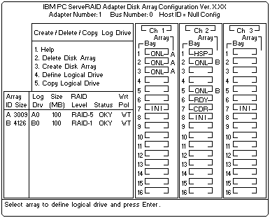
The first drive marked RDY (ready) will be highlighted. Be certain not to use drives shared on the other side , Server A. Arrays and logical drives can only be defined to one adapter.
You must not create arrays from drives used in logical drives created in the other server.
If both adapters try to manage the same drives, one of the adapters will place the drives in the DDD (defunct) state.Note: When creating shared arrays, make sure all drives selected are connected to shared channels.
- Press Enter to include the other drives that were currently marked as RDY in the array.
- Press Esc to complete the selection and to create the array.
- After the array has been created, each drive will be designated as ONL with an array letter assigned to it, for example: A, B, or C.
- Select Define Logical Drives and press Enter. A screen similar to the following appears.

- Use the Up Arrow (
 ) or Down Arrow (
  ) keys to select the array for the new logical drive; then, press Enter.
- Use the Up Arrow (
 ) or Down Arrow (
  ) keys to highlight the RAID level you want to assign to
the logical drive; then, press Enter.
- When a screen prompt appears requesting the size of the logical drive, accept the maximum
value; then, press Enter.
Only one logical drive per RAID array is supported for shared drives. - When the Confirm pop-up window appears, select Yes; then press Enter.
- When a message stating that all logical drives must be initialized appears, press any key to continue.
Note: To ensure that your server operates correctly, you must initialize the new logical drive.
 -Attention- A quick initialization of a logical drive erases the first 1024 sectors on the drive
and prevents access to any data previously stored on the drive; therefore, be sure not to
initialize any logical drives which were previously defined and contain valid data.
For more information about initialization, refer to the 'IBM ServeRAID Adapter Installation and User's Guide'. - When the Confirm pop-up window appears, select Yes to perform a quick initialization; then, press
Enter and follow any instructions that appear on the screen.
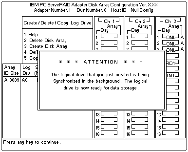
Note: If you have created a RAID level-5 logical drive, when you press the Esc key, synchronization automatically begins and a screen similar to the following appears.
Note: When creating shared arrays, make sure all drives selected are connected to shared channels. - When complete, press the Esc key until you return to the Main Menu of the configuration program.
- Repeat (above) step 4 for each additional array and logical drive you want to define; then, continue with (below) step 5.
Note: Shared logical drives must have unique Merge IDs; however, nonshared logical drives can share the same Merge ID.
- Select Advanced Functions from the Main Menu of the configuration program.
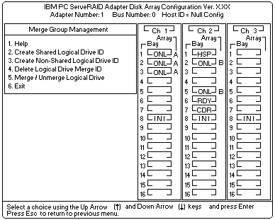
- Select Merge Group Management from the Advanced Functions menu.
- To create nonshared Merge IDs, do the following:
1) Select Create Nonshared Logical Drive ID. from the Merge Group Management Menu.
2) Select the logical drive you want to make a nonshared drive by using the Up Arrow ( )
)
or Down Arrow ( ) keys to highlight the drive; then, press the Enter key.
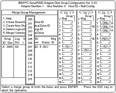
3) Select the Merge ID from the Selection List.Note: A shared logical drive and a nonshared logical drive cannot be on the same array.
Valid Merge IDs for nonshared logical drives are in the range 200-215.
An example would be to set all nonshared drives on Server A to Merge ID 206 and all nonshared drives on Server B to Merge ID 207.
4) When complete, press the Esc key and save all the changes.
1) Select Create Shared Logical Drive ID from the Merge Group Management menu.

2) Select the logical drive you want to be shared between the two servers by using the Up Arrow
(
 ) or Down Arrow (
  ) keys to highlight the drive; then, press the Enter key.
3) Select the Merge ID from the Selection List.
The Merge ID must be unique for each shared logical drive that will be shared by each
adapter pair.
For example, if you have a logical drive with a merge ID of 1 on the first ServeRAID
adapter in a server pair, you cannot assign the same merge ID to a logical drive on the
second adapter in a server pair. Valid IDs for shared logical drives are in the range 1-8.

4) Repeat (above) step 5 for each shared logical drive you want to create.
